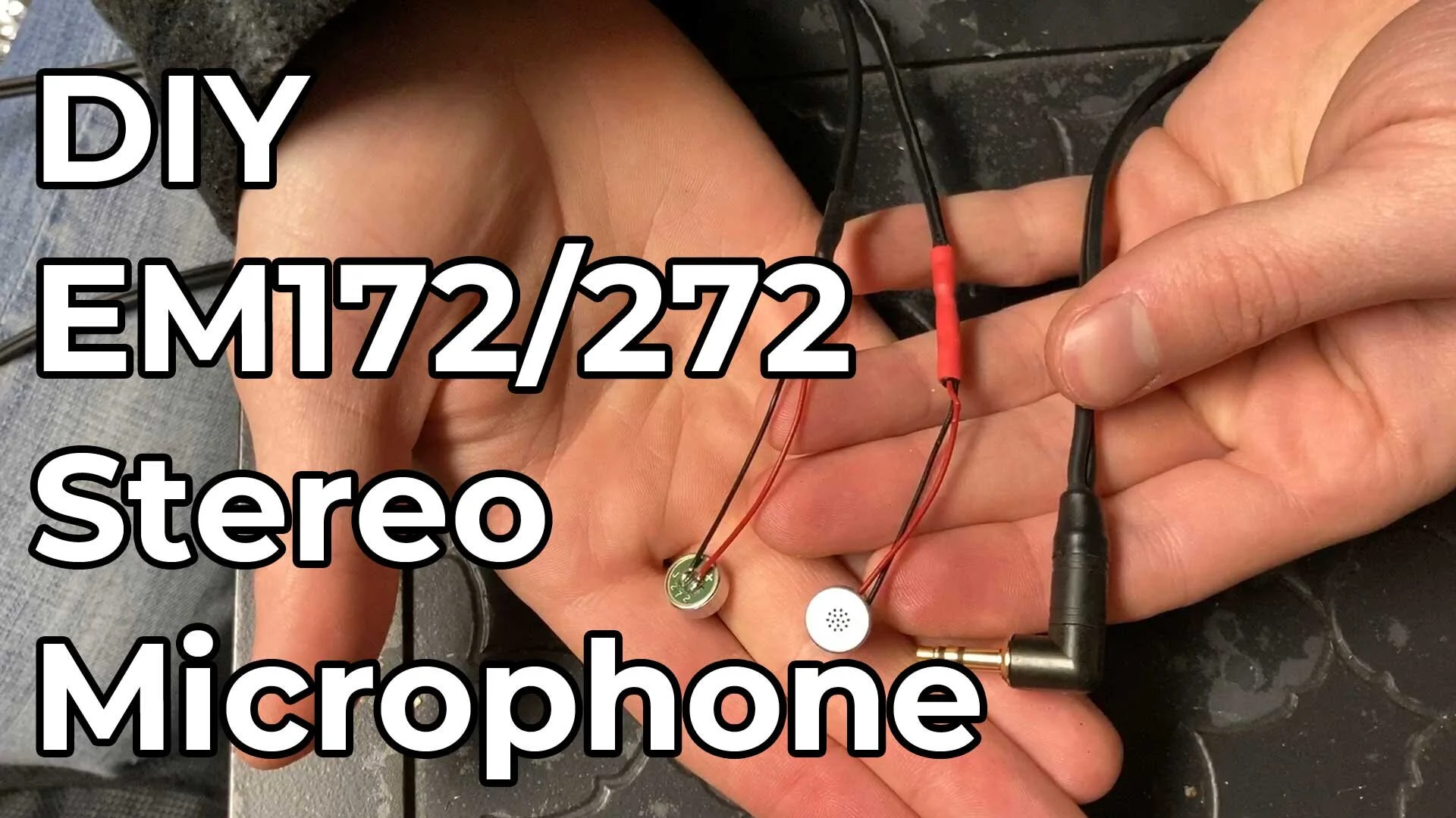
How To Make DIY Microphone With EM172/272 Capsules
Learn how to build your own ultra low-noise microphone with EM272 capsules in this article!
In the world of custom microphone building, the Primo EM172 capsules are among the most popular mics to use. They have gained such popularity thanks to their ultra low-noise specifications that compete with commercial microphones costing thousands of dollars.
With a matched pair costing about $50, it’s easy to understand their popularity.
Recently, Primo upgraded and replaced the beloved EM172 capsule with the new EM272 capsule. The EM272 has the same low-noise specifications and high sensitivity of the EM172 but comes equipped with additional RF protection.
When I first started field recording, I was on a quest to get the best quality sound on a low budget. I quickly learned about the EM172 capsules and built myself my first stereo microphone with them. While the sounds were incredible, my electrical skills weren’t.
Over the years, I’ve built several microphones using the EM172 and EM272 microphones. I have learned a lot and wanted to create this step-by-step guide to help beginners feel confident enough to give DIY mic making a shot.
This article features a video and detailed, step-by-step instructions on how to make a low-noise stereo microphone from EM272 capsules. Enjoy!
DIY Microphone Build Video
Materials List
Here are links to all the products that I use in this build guide. If you need to purchase any of these items and would like to support this site, please consider using the links below. They are affiliate and help me to keep Acoustic Nature running. Thank you for your support!
Soldering Iron: Check Price
Electrical Solder: Check Price
Audio Cable: micbooster.com
Wire Stripper: Check Price
Helping Hands: Check Price
90° 3.5mm Plug: Check Price
Heat Shrink: Check Price
Electrical Tape: Check Price
DIY Microphone Instructions
In total, there are 20 steps. That’s probably more than necessary, but I wanted to make sure that this guide was clear and comprehensive. If you have any questions, or would like clarification about any steps, please ask me via the contact page on my website.
Step 1
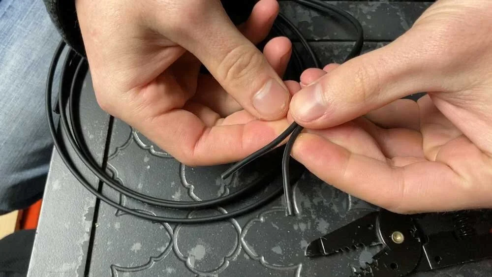
After cutting your cable to your desired length, split the cable into 2 parts.
Split the figure 8 cable in half. You may need to make a small cut using wire snips, scissors, or a razor blade to start the split. From there, the cable will easily split by pulling it apart.
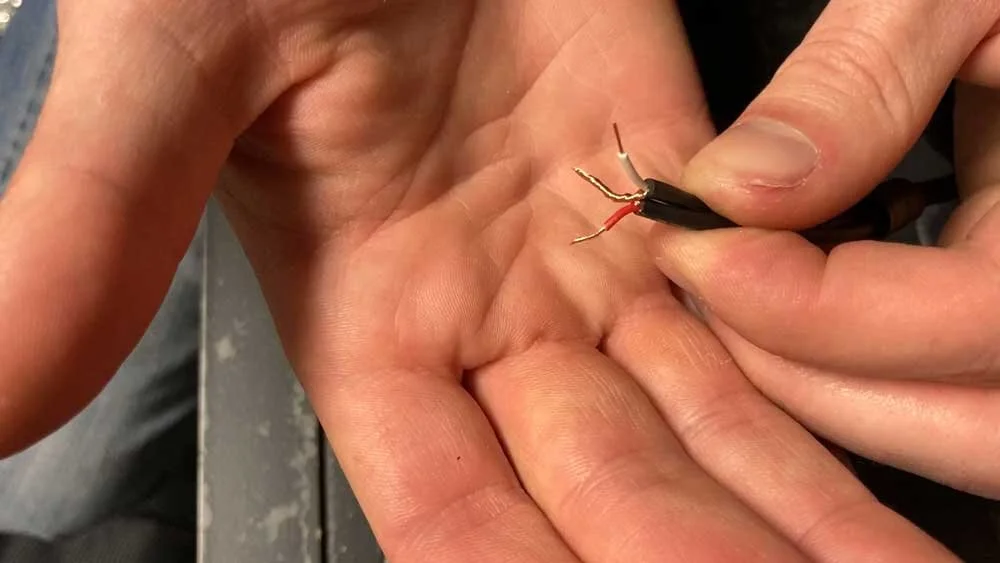
Step 2
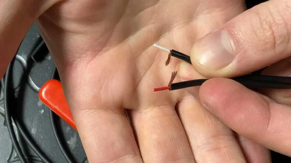
Using wire strippers, strip about 1 cm from each wire.
Use your wire strippers to strip about 1 cm from each wire. Once removing the outer jacket, you’ll notice that the copper shield wires are tightly wrapped around the central conductor (red/white wire). Use your fingers to pull the copper shield to one side of the conductor, as pictured above.
Step 3
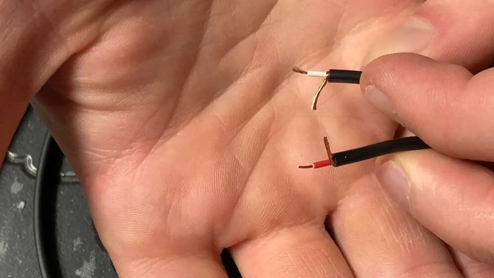
Strip ≈ 4mm from each conductor and twist wires together.
Strip about 4mm from each conductor and twist the exposed wires together with your fingers.
Step 4
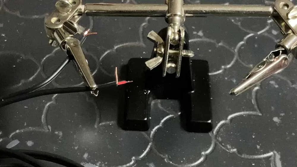
Clamp one wire in the helping hands vice.
Clamp one of the wires in the helping hands vice. The vice will make soldering this wire to the EM272 capsule much easier.
Step 5
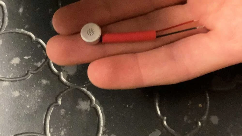
Slide heat shrink over the EM272 leads.
Slide roughly a 1” length of heat shrink over the EM272 wires. The heat shrink tubing can not be added after soldering so don’t forget!
This will be my right channel mic so I’m using red heat shrink. I will use black heat shrink on my left mic. This way, I can easily tell which is which in the field.
Step 6
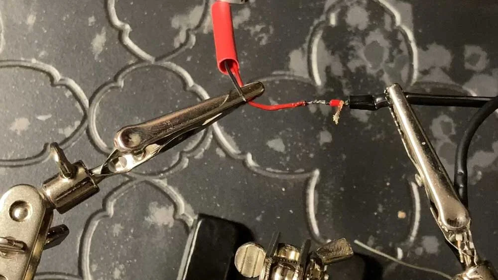
Clamp the red EM272 wire in the helping hands vice and align the two wires on top of one another.
This step can be finicky, but it’s worth spending the time to get your wires as close together as possible. You’ll thank yourself in the next step.
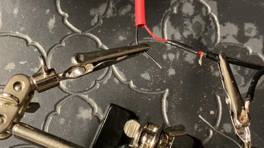
Step 7
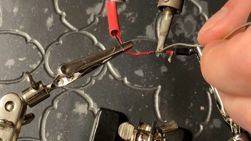
Solder the 2 red wires together.
Use a soldering iron to heat the wires from below and rest your solder on top of the wires. When the wires are hot enough, the solder will melt and wick into the connection, creating a strong bond.
Step 8
Wrap the connection with electrical tape.
Wrapping this connection in electrical tape prevents it from touching the shield wires. If this were to happen, the connection would short out.
Step 9
Repeat steps 4-7 for the left channel EM272. No electrical tape is necessary for this connection.
Step 10
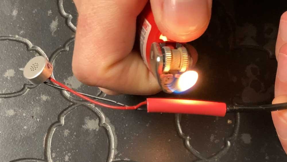
Slide heat shrink over soldered connections and heat with a lighter.
To avoid burning the heat shrink, do not let the flame directly contact the heat shrink and apply even heat. Direct flame can get soot on the heat shrink that is difficult to remove. Prolonged heat in one area can melt the heat shrink causing an undesirable bubbled appearance and terrible smell.

Heat shrink after applying heat.
Step 11
Repeat step 10 on the other microphone connection.
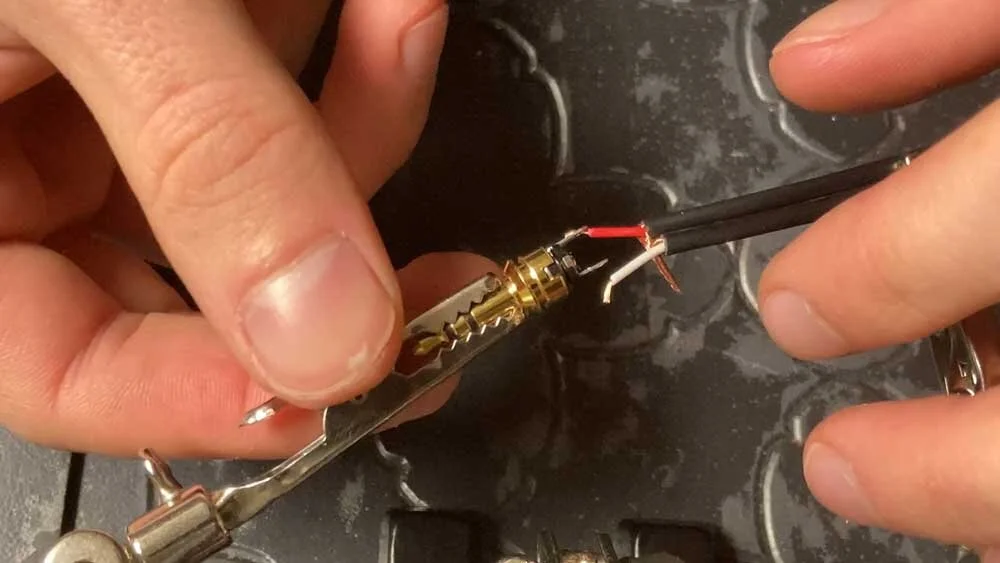
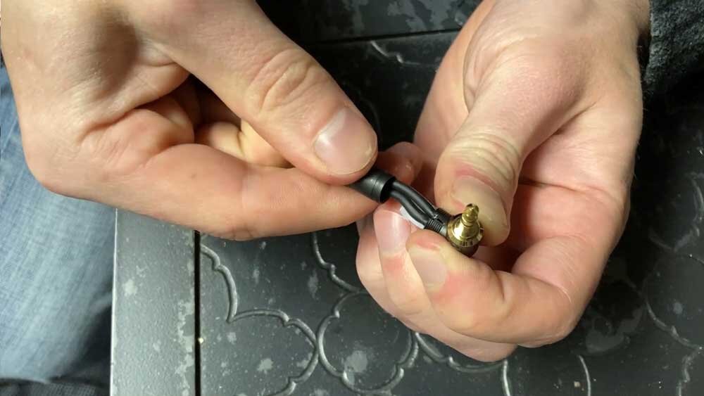
Step 12
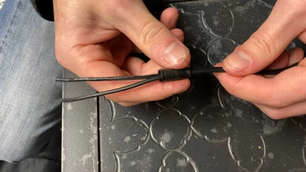
Slide the barrel connector over the terminating wire ends.
Most 3.5mm connectors will have a barrel or bushing connector that must be installed before soldering any connections. If you’re using the cable and 3.5mm connector I am, you’ll find that this step is a tight squeeze.
That’s because the Neutrik Right-Angled Plug is rated for a maximum cable diameter of 4.5mm and our cable is 5mm. However, with a little patience, it can be done and is not a problem.
Step 13

Follow your connector’s instructions to strip the appropriate length from each wire.
Your 3.5mm connector should come with cable preparation instructions that tell you exactly how long each wire needs to be. The instructions for the right-angled connector I’m using are below.
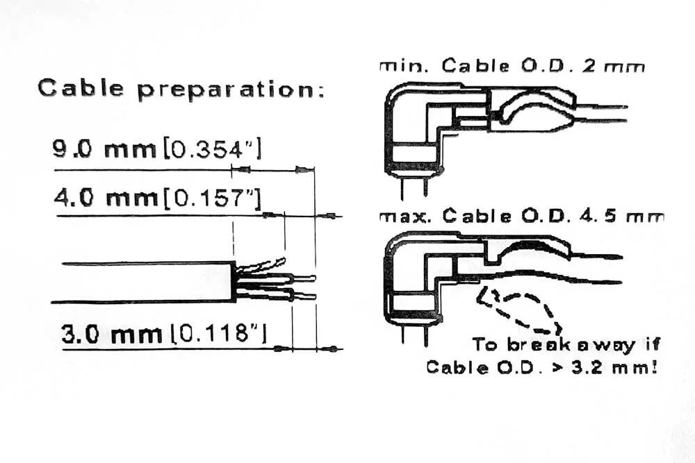
The cable preparation instructions for the Right-Angled Neutrik Connector.
For this connector, start by stripping 9mm from each wire. Then, separate the shield wires and trim them to 4mm in length. Next, strip 3mm from each conductor wire.
Step 14
Twist the 2 copper shield wires together to form 1 wire.
Step 15
Put 3.5mm connector in clamp and thread red conductor through the ring hole.
The 3.5mm connector is formally called a TRS plug. The acronym stands for Tip, Ring, Sleeve. These names correspond to the 3 connections of an unbalanced audio signal: left, right, and shield.
Look at the diagram below for a wiring diagram for the Neutrik Right-Angled TRS Plug.
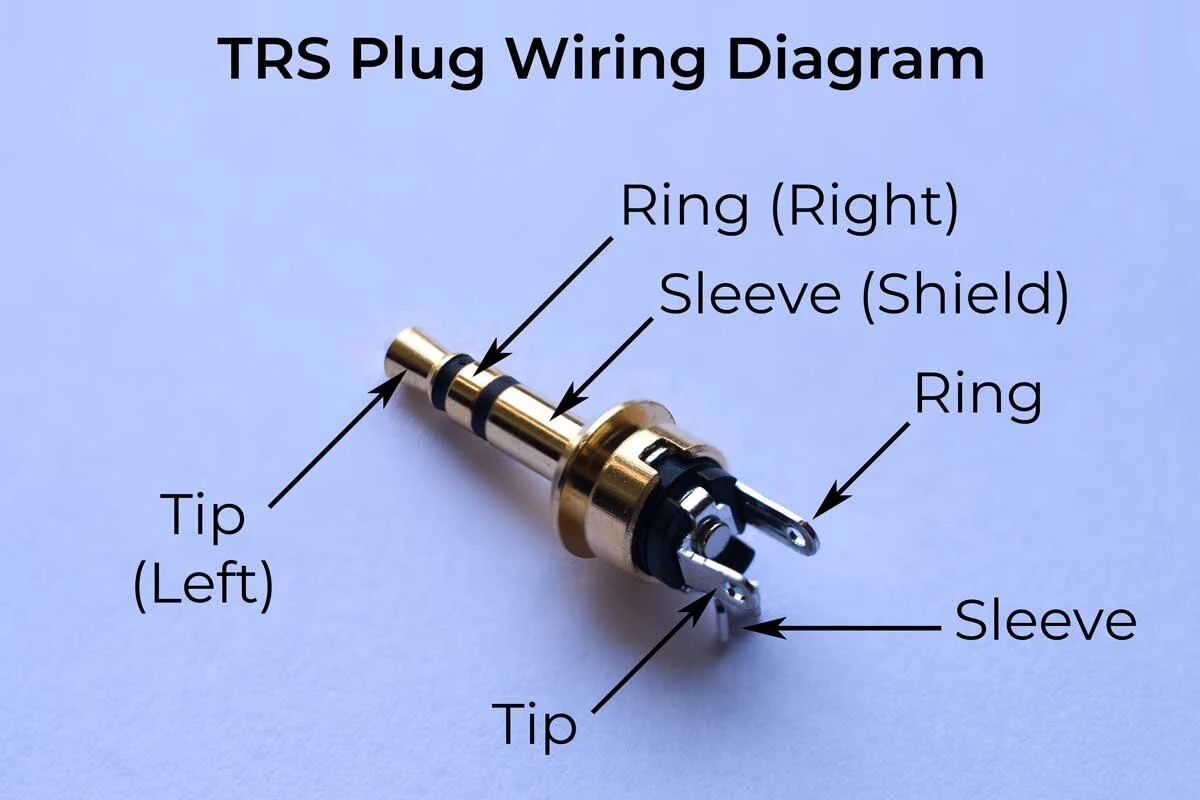
When you thread the red conductor wire through the hole in the ring tab, make sure that the insulation (red part of the wire) goes all the way to the tab. This will ensure that no bare wire is exposed past the connection point, and will prevent any shorts.
Step 16
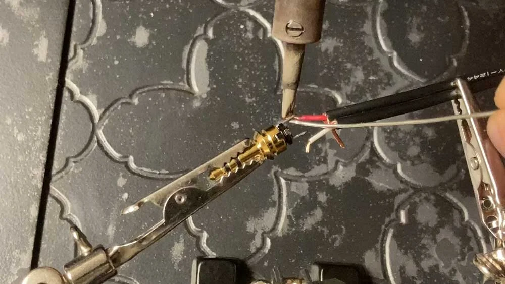
Solder the red conductor to the ring.
Apply heat with a soldering iron to the outside of the ring connector tab and rest solder against the inside of the tab. Once the tab gets hot enough, the solder will melt and create a perfect connection.
Step 17
Repeat steps 15-16 to solder the left channel (white conductor wire) to the TRS tip.
Step 18
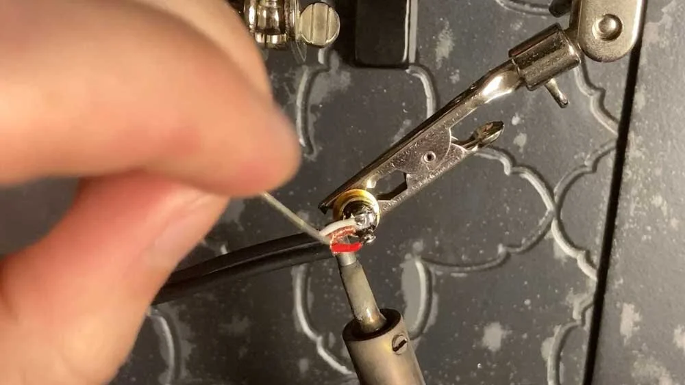
Solder the shield wire to the sleeve tab on the TRS plug.
As pictured, I found clamping the TRS plug in the vice vertically helpful for this step. Heat the backside of the tab with a soldering iron and push down on the shield wire with a strand of solder. Once hot enough, the solder will melt right into this connection.
If your shield wire doesn’t want to stay in place, try the following. Melt solder into the connection, continue to apply heat with soldering iron, use a pencil/pen/small screwdriver to push the shield wire down. Then, while still applying downward pressure with your pointy object, remove the soldering iron and wait a few seconds. The solder will quickly solidify and hole the wire in position.
Step 19
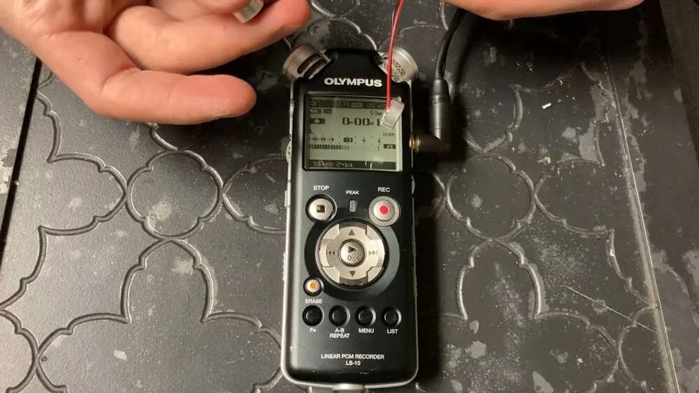
Make sure it works!
Before finishing the assembly of the connector, now is a good time to test the microphones. Carefully plug the unfinished 3.5mm plug into your recorder. Turn on plug-in-power. Start a recording and test each microphone capsule.
Note: the above image shows the connector completed. I did not get a shot of me testing the microphone before its completion.
Step 20
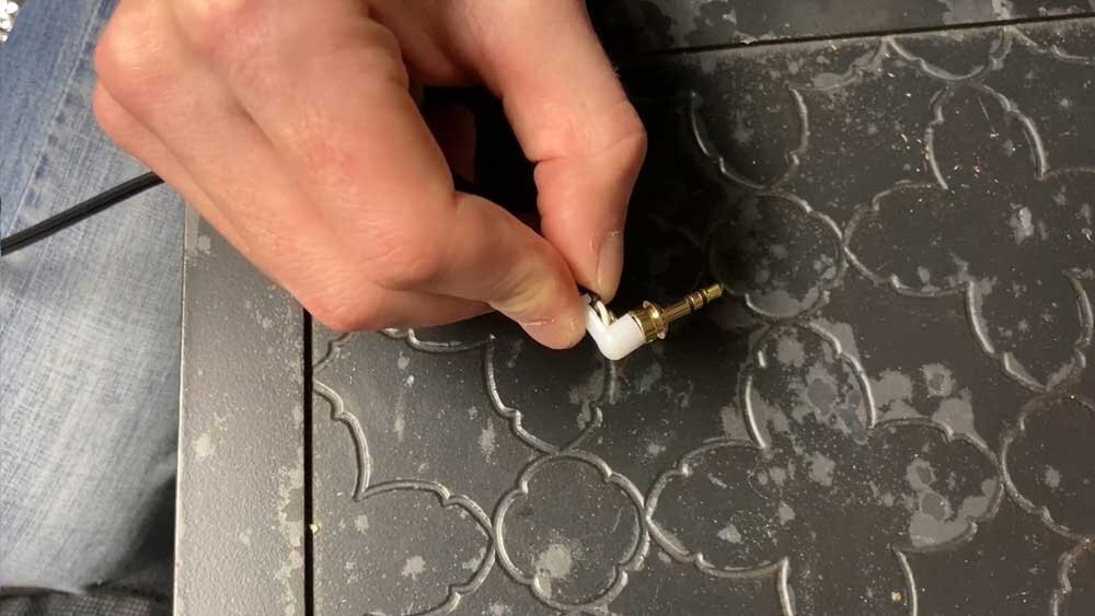
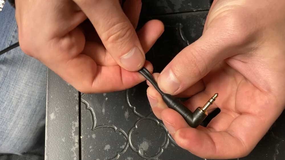
Assembling the rest of the connector is pretty easy.
Attach the plastic chuck over the soldered connections.
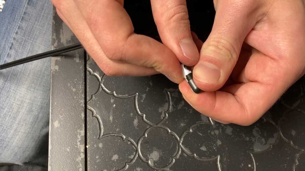
Place the 2 metal shell halves on either side of the plastic chuck.
Slide the barrel up to the threads and tighten it.
The completed connector.
That’s It, You’re Done!
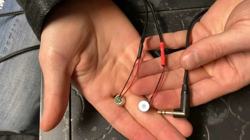
The completed microphone.
Congratulations, you have successfully made yourself an ultra low-noise microphone!
If you have any questions about this project, feel free to ask me through the contact page on my website.
Support Acoustic Nature
If you enjoyed this post and would like to help support Acoustic Nature, please consider "buying me a coffee" or becoming a Patreon with the buttons below.
As a thank you for your support, Patreon supporters receive a copy of Field Recording For Beginners, exclusive access to the full Behind The Sounds video series, nature sound library downloads, and more.
If you are unable to support the site financially, please share this post with others, or leave a comment below letting me know you enjoyed this post! Both are free and help the website grow. Thank you ♫
Thanks for reading,
-Jared